Project Detail

Home – Project Detail

Inverter Output Voltage 100Vac, 110Vac, 120Vac, 220Vac, 230Vac, 240Vac (optional)
AC Input Voltage 90-264Vac
AC Frequency Range 47-63Hz
Storage temperature -40°C~+70°C
Cooling Method Forced air cooling
IP rating Ip20
MTBF 250KHrs, 25°C, 80% load
Weight Max.4Kg


The BIM series 3000-3600-4200W is a multi-functional bidirectional PCS module, which adopts a high-efficiency soft-switching patented topology and digital control technology. It integrates a pure sine wave inverter, high-power charger, UPS bypass, RS485 and CAN communication ports, parallel operation and other functions.

Function Description:

  • Standby Mode:
    • The module is in standby state, waiting for instructions from the host computer.
  • Automatic Working Mode:
    • This mode supports automatic charging and discharging, with charging via the auxiliary path taking priority and grid-connected inversion taking precedence when off-grid.
    • Charging State:
      1. When the auxiliary path is not activated, the battery charging power takes the value set by the host computer’s instruction power.
      2. If the auxiliary path is loaded, the host computer needs to calculate the remaining power for battery charging based on the current that the AC input cable can withstand.
      3. If the auxiliary path has no load, charge the battery according to the instruction power.
    • Off-grid Inversion State:
      1. If there is no AC grid connection, supply power to the load through the auxiliary path and disconnect from the grid side.
      2. If the grid is connected or restored during the discharging process, and the voltages are equal or close, the auxiliary path can automatically switch to the grid connection, with the grid supplying power to the load. Meanwhile, the monitoring version needs to calculate the remaining power for battery charging based on the input current. If the voltages are not equal, inversion output takes precedence.
  • DC Current Limit Point Adjustment:
    • Can only be used in PCS charging mode. Adjusted via instructions sent by the host computer, it can be continuously adjusted with a minimum adjustment step of 0.1A. The DC current limit point is adjustable between 0~Max.
  • DC Voltage Adjustment:
    • Can be used in both PCS charging and inversion modes. Adjusted via instructions sent by the host computer, it can be continuously adjusted with a minimum adjustment step of 0.1Vdc. The DC voltage is adjustable between 40V-59.5V.
  • Battery Over-discharge Activation:
    • In the case where the matched battery over-discharge protection does not output, the PCS can realize the battery activation function. Specific measures: When the PCS detects AC power input and the voltage is within the normal range, if there is no communication within 5 seconds, the PCS will automatically start up, set the maximum charging voltage to 40V and the charging current limit to 3A by itself, charge the battery, and wait for the host computer to wake up and send new charging instructions.
  • Fan Control:
    • The module is cooled by air. The fan speed is intelligently adjusted based on the ambient temperature and power to achieve energy saving and ultra-low noise. The current speed percentage can be read in real time.
  • Output Power Limit Control:
    • The bidirectional module has two working modes: rectification (charging) and inversion. The output power is the same in both modes.

Product Specification Parameters:

Module Function Model BIM48-3000 BIM48-3600 BIM48-4200
Output Function
Inverter Power 3000W 3600W 4200W
Charging Power 3000W 3600W 4200W
Inverter Output Voltage 100Vac, 110Vac, 120Vac, 220Vac, 230Vac, 240Vac (optional) 220Vac, 230Vac, 240Vac (optional)
Inverter Output Frequency 50Hz, 60Hz (optional)
Inverter Overload Capacity 100%<P<=110% peak power, duration 20s
110%<P<=125% peak power, duration 5s
125%<P<=150% peak power, duration 2s
150%<P<=200% peak power, duration 200ms
100%<P<=150% peak power, duration 2s
150%<P<=200% peak power, duration 200ms
200% peak power
Output Waveform Pure sine wave
ThdU 3%@resistive load
Efficiency Max.91.2%@120Vac, Max.93.5%@220Vac Max.93.5%@220Vac
Start-up Supports 6 units of wired parallel operation
Rectification (Charging) AC Input Voltage 90-264Vac 176-264Vac
AC Frequency Range 47-63Hz
Maximum AC Input Current 30A (放宽至30A,but system design needs to consider regulations, e.g., maximum AC input 15A in the US, domestic maximum AC input current set to 16A)
PF 0.99@100%Load
ThdI <5%@100%Load
Maximum Charging Current 60A 72A 80A
Charging Voltage Range 40-59.5Vdc
Voltage Ripple Max.700mV (0-20MHz)
Efficiency Max.92.5%@120Vac, Max.94.5%@220Vac Max.94.5%@220Vac
Charging Management Managed by host computer
Ac Bypass Switching Ac Bypass Current Max.15A
Switching Time Typical 20ms
Environmental Conditions Operating Temperature -25°C ~ +70°C, derating above 45°C
Storage Temperature -40°C ~ +70°C
Relative Humidity ≤95%RH, no condensation
Cooling Method Forced air cooling
Altitude 2000m, for altitudes above 2000m, derate by 1°C for every 200m increase in altitude.
Atmospheric Pressure 79kPa ~ 106kPa
Response Time Max.10S (from host computer sending instruction to output)
Leakage Current Max.10mA
Insulation Resistance Insulation resistance between DC part, AC part and outer casing, and between AC part and DC part ≥10MΩ
Noise Max.58dB (1m)
Others Insulation Strength AC terminal to casing:
1500Vac/50Hz or 2120Vdc60S, no breakdown, no flashover, steady-state leakage current <10mA;
AC terminal to DC terminal:
3000Vac/50Hz or 4240Vdc60S, no breakdown, no flashover, steady-state leakage current <10mA;
DC terminal to casing:
500Vac/50Hz or 710Vdc60S, no breakdown, no flashover, steady-state leakage current <10mA;
AC terminal to CAN or 485 terminal:
3000Vac/50Hz or 4240Vdc60S, no breakdown, no flashover, steady-state leakage current <10mA;
DC terminal to CAN or 485 terminal:
500Vac/50Hz or 710Vdc60S, no breakdown, no flashover, steady-state leakage current <10mA;
Casing to CAN or 485 terminal:
500Vac/50Hz or 710Vdc60S, no breakdown, no flashover, steady-state leakage current <10mA;
Grounding Resistance Grounding resistance ≤0.1Ω, withstand current ≥50A
Safety Regulations TBD
EMC EN55032, EN55035, IEC61000-3-2, IEC61000-3-3, FCC
MTBF 250KHrs, 25°C, 80% load
Weight Max.4Kg


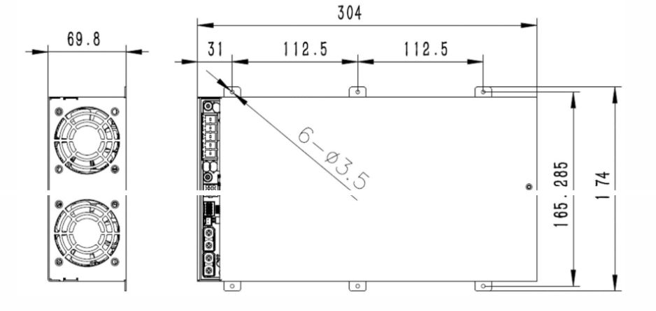
Installation Instructions: Module installation and fixation There are 3 installation holes on each side of the entire module. They are fixed by 3 M3 screws. The specific installation dimensions are shown in the following figure:


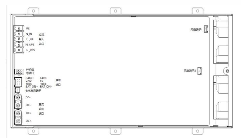
Module input/output terminal description:

Project Overview

SunCare Hospital, a leading healthcare institution committed to sustainable operations and patient well-being, partnered with us to transition its energy source to solar. The project involved the full design and installation of a customized solar power system to reduce operating costs, increase energy reliability, and support the hospital's green initiatives.

Project Objectives

This project was designed to meet the hospital’s energy needs while promoting sustainability, reducing costs, and ensuring uninterrupted service for patients and essential medical operations.

Key Results & Benefits

What We Delivered

We provided a complete solar solution tailored to the hospital’s needs, ensuring performance, safety, and long-term energy savings without disrupting daily operations.

Custom Energy Assessment

We analyzed usage patterns and infrastructure to design a system that meets specific energy needs.

Seamless Installation Without Disruption

Our team installed efficiently with zero interruption to hospital operations and strict safety procedures.

Tailored Solar System Design

We created a solar layout that maximizes efficiency while matching the hospital’s structure and goals.

Reliable Backup and Monitoring System

We integrated smart monitoring and backup support to ensure continuous power for critical medical equipment.

Our Impact

This project is more than just an energy upgrade, it is a commitment to health, sustainability, and community leadership. The SunCare Hospital solar installation reflects how renewable energy can enhance essential services without compromise.

Client Testimonial

"Working with Solarize was a smooth experience. Their team truly understood our hospital’s needs and delivered a solution that saves energy, ensures reliability, and supports our long-term sustainability goals."

Dr. Lisa
Director of Operations, SunCare Hospital
Other Projects

Energizing Communities Through Innovation

Solarize brings cutting-edge clean energy solutions to life, empowering homes, businesses, and public spaces with sustainable power that transforms everyday living.

BrightMall Complex

Location: Lisbon, Portugal
Solar rooftop installation across a large-scale shopping mall to reduce grid dependency and promote sustainable retail operations. Integrated with smart energy monitoring for maximum efficiency.

SunCare Hospital

Location: Melbourne, Australia
Development of a solar-battery hybrid system for uninterrupted power in critical hospital zones, including ICUs and emergency rooms. Designed to meet high safety and reliability standards.

EcoBank Tower

Location: Nairobi, Kenya
Solar façade and rooftop system installed on a 20-story corporate office building, integrated with energy-efficient HVAC systems to reduce operational carbon footprint.

GreenForge Factory

Location: Hamburg, Germany
Large-scale solar installation for a metal fabrication plant, optimized to meet industrial energy demand while supporting Germany’s renewable transition goals. Includes automated load balancing.