Home – Project Detail
| Output Voltage Range | 260VAC-530VAC |
| Efficiency | ≥95.8% |
| Rated Output Current | 0A-133A |
| Frequency | 45Hz ~ 65Hz |
| Working Environment Temperature | -40°C ~ +75°C normal operation; |
| Dimensions | 110mm (height) × 385mm (width) × 390mm (depth) excluding socket and handle |
| Module Net Weight | ≤22.5kg |
| Communication Interface | CAN |
| Maximum Parallel Quantity | 60 units |
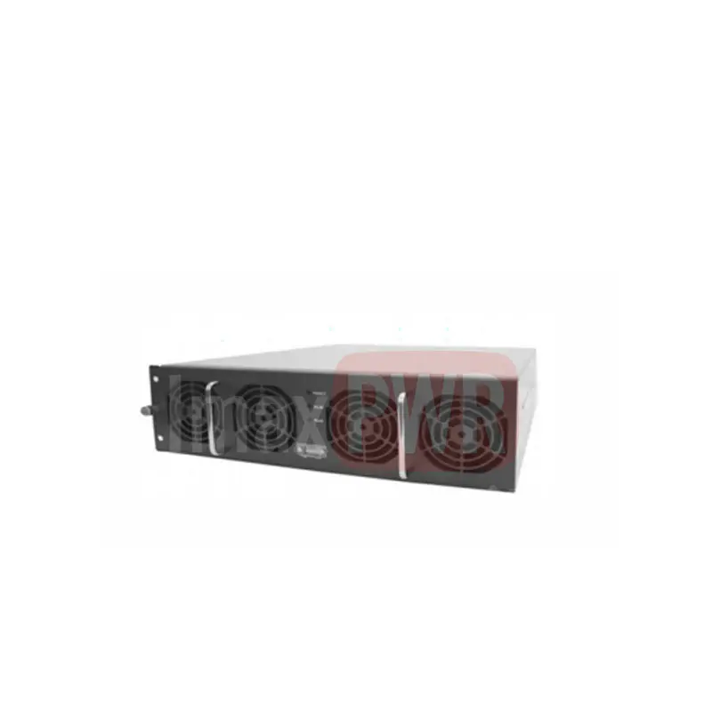
The SEG series module is a high-performance DC charging module. Its main function is to rectify the three-phase AC input from the power grid into a DC output, providing a fast DC charging current for electric vehicle batteries. It can also be used to provide stable voltage and current for equipment. Including 30KW100A1000V and 40KW133A.
The internal circuit of the module is mainly divided into two parts.
The first part is responsible for rectifying the wide-range three-phase AC input voltage into an internal high-voltage bus, and completing the correction of indicators such as PF and THD.
The second part is responsible for converting, isolating, and rectifying the internal high-voltage bus, and outputting the corresponding DC voltage/current based on different monitoring settings.
● Product Features:
● Product Specification Parameters:
| Category | Name | Parameters |
|---|---|---|
| Environmental Conditions | Operating Temperature | -40°C ~ +75°C, derate above 55°C |
| Storage Temperature | -40°C ~ +70°C | |
| Relative Humidity | ≤95% RH, no condensation | |
| Cooling Method | Forced air cooling | |
| Altitude | ≤2000m, derate above 2000m | |
| Atmospheric Pressure | 79kPa ~ 106kPa | |
| IP Protection Rating | Ip20 | |
| AC Input | Input Mode | Three-phase + PE |
| Voltage Range | 260Vac~530Vac | |
| Maximum Static Voltage Endurance (Non-operating) | 600Vac | |
| Rated Voltage | 380Vac | |
| Maximum Current | 80A | |
| Grid Frequency | 45Hz~65Hz | |
| Rated Frequency | 50Hz/60Hz | |
| DC Output | Voltage Range | 150Vdc ~ 1000Vdc |
| Current Range | 0 ~ 133A (current limit point can be set) | |
| Rated Current | 40A (current limit point setting required) | |
| Voltage Stabilization Accuracy | < ±0.5% (150~1000V, 0~20MHz) | |
| Current Stabilization Accuracy | ≤±1% (output load 20% ~ 100% of rated range) | |
| Load Adjustment Rate | ≤±0.5% | |
| Grid Adjustment Rate | ≤±0.1% (test range 320~530V) | |
| Start-up Overadjustment | ≤±3% | |
| Voltage Ripple | Voltage Ripple Peak Factor | ≤1% (150~1000V, 0~20MHz) |
| Power Factor and THD | Power Factor | ≥0.90 @ 25%~50% full-load output power |
| ≥0.98 @ 50%~100% full-load output power | ||
| ≥0.99 @ 100% full-load output power, standard input voltage and frequency | ||
| THD | ≤5% @ 50%~100% full-load output power |
| EMC Indicators | Name | Parameters/Standards |
|---|---|---|
| Ripple, EFT | Requirement | Meets the general technical specifications for DC charging machines for non-vehicle-mounted electric vehicles, NB/T 33001-1-2018, NB/T 33008-1-2018 |
| Conducted Disturbance | Limit | 3Vrms, 0.15~80MHz Reference standard: NB/T 33001-1-2018, NB/T 33008-1-2018 |
| ESD | Limit | 8kV/15kV; Reference standard: NB/T 33001-1-2018, NB/T 33008-1-2018 |
| Radiated Disturbance | Limit | 10V, 80~2GHz; Reference standard: NB/T 33001-1-2018, NB/T 33008-1-2018 |
| Power Frequency Magnetic Field | Limit | 30A/m; Reference standard: NB/T 33001-1-2018, NB/T 33008-1-2018 |
| Conducted Emission | Limit | Class A, meets the general technical specifications for DC charging machines for non-vehicle-mounted electric vehicles, NB/T 33001-1-2018, NB/T 33008-1-2018 |
| Radiated Emission | Limit | Class A, meets the general technical specifications for DC charging machines for non-vehicle-mounted electric vehicles, NB/T 33001-1-2018, NB/T 33008-1-2018 |
| Safety Requirements | Requirement | Meets the general technical specifications for DC charging machines for non-vehicle-mounted and vehicle-mounted electric vehicles, NB/T 33001-1-2018, NB/T 33008-1-2018 |
| Efficiency | Value | ≥95.8%, @1000V, full load, rated three-phase input voltage conditions |
| Weighted Efficiency | Value | ≥94.5%, @300V, 380V, 470V, 530V, 670V; Corresponding to the efficiency at maximum output current, with weighting ratios of 3:2:2:1:2 |
| Inrush Current at Startup | Limit | <102A |
| Mean Current | Limit | At 10%~100% load, the mean current error of the module is ≤±5% of the rated output current |
| Temperature Coefficient (1/°C) | Limit | ≤±0.01% |
| Startup Time (select startup mode via monitoring module) | Description | Normal startup mode: time delay from DC on to module output ≤3s Output buffer: startup time can be set via the monitoring module, default output startup time is 3~8s |
| Grounding Resistance | Limit | Grounding resistance ≤0.1Ω, withstand current ≥80A |
| Leakage Current | Limit | Leakage current ≤3.5mA |
| Insulation Strength | Test Conditions & Limits | AC input terminal to CAN 4242V DC voltage for 1 minute, no breakdown, no arcing phenomenon, steady-state leakage current <1mA; AC input terminal to slave control signal 4242V DC voltage for 1 minute, no breakdown, no arcing phenomenon, steady-state leakage current <1mA; AC input terminal to chassis 3535V DC voltage for 1 minute, no breakdown, no arcing phenomenon, steady-state leakage current <1mA; AC input terminal to DC output terminal 3535V DC voltage for 1 minute, no breakdown, no arcing phenomenon, steady-state leakage current <1mA; DC output terminal to chassis 3535V DC voltage for 1 minute, no breakdown, no arcing phenomenon, steady-state leakage current <1mA; DC output terminal to CAN 4242V DC voltage for 1 minute, no breakdown, no arcing phenomenon, steady-state leakage current <1mA; DC output terminal to slave control signal 4242V DC voltage for 1 minute, no breakdown, no arcing phenomenon, steady-state leakage current <1mA; CAN to chassis 707V DC voltage for 1 minute, no breakdown, no arcing phenomenon, steady-state leakage current <1mA |
| ROHS | Standard | R5 |
| Mechanical Parameters | Size | 110mm (height) × 385mm (width) × 390mm (depth) excluding socket and handle |
| Weight | ≤22.5kg |
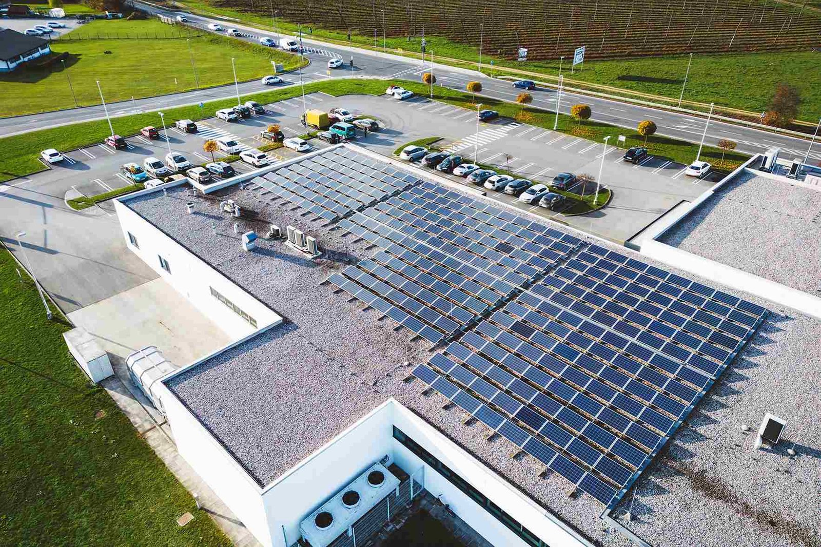
SunCare Hospital, a leading healthcare institution committed to sustainable operations and patient well-being, partnered with us to transition its energy source to solar. The project involved the full design and installation of a customized solar power system to reduce operating costs, increase energy reliability, and support the hospital's green initiatives.
This project was designed to meet the hospital’s energy needs while promoting sustainability, reducing costs, and ensuring uninterrupted service for patients and essential medical operations.

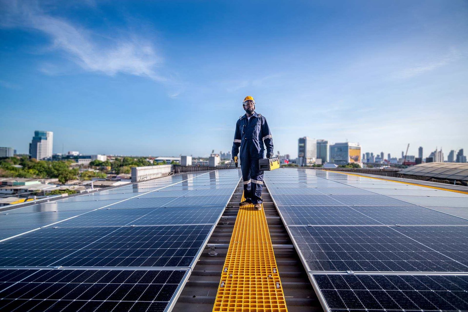
We provided a complete solar solution tailored to the hospital’s needs, ensuring performance, safety, and long-term energy savings without disrupting daily operations.
We analyzed usage patterns and infrastructure to design a system that meets specific energy needs.
Our team installed efficiently with zero interruption to hospital operations and strict safety procedures.
We created a solar layout that maximizes efficiency while matching the hospital’s structure and goals.
We integrated smart monitoring and backup support to ensure continuous power for critical medical equipment.
This project is more than just an energy upgrade, it is a commitment to health, sustainability, and community leadership. The SunCare Hospital solar installation reflects how renewable energy can enhance essential services without compromise.

Solarize brings cutting-edge clean energy solutions to life, empowering homes, businesses, and public spaces with sustainable power that transforms everyday living.